🔧 How to Build a High-Intensity LED Flash Circuit with CD4093 and Basic Transistors
Looking to create a simple yet powerful LED strobe or flash using just a few components? In this project, we’ll show you how to build a high-brightness LED flash circuit using a CD4093 NAND gate IC, one 2N3906 PNP transistor, and one **2N2222 ...
This circuit is perfect for hobbyists who want a quick and efficient solution without complex components.
📷 Circuit Overview
The core of the design is the CD4093, a quad NAND gate Schmitt trigger. Here's how the circuit functions:
-
IC1/A and IC1/B are wired as inverters, forming an oscillator that outputs a square wave.
-
This signal is used to alternately switch two transistors:
-
TR1 (PNP 2N3906) receives input from IC1/B.
-
TR2 (NPN 2N2222) is driven by IC1/C.
-
-
The high-brightness LED (DL1) is connected between R7 and the collector of TR2.
-
The frequency of the flashes can be adjusted using R2, a 4.7M trimmer.
Power the circuit with a DC voltage between 12V and 15V, and enjoy a customizable LED flash effect.
🧩 Complete Component List
| Component | Value / Type |
|---|---|
| R1 | 2.2MΩ |
| R2 | 4.7MΩ trimmer |
| R3 | 2.2kΩ |
| R4 | 10kΩ |
| R5 | 2.2kΩ |
| R6 | 100Ω |
| R7 | 100Ω |
| TR1 | PNP 2N3906 |
| TR2 | NPN 2N2222 |
| IC1 | CD4093 |
| DL1 | High-Brightness LED |
| S1 | Toggle Switch |
🔁 You can replace TR1 and TR2 with any general-purpose PNP and NPN transistors if needed.
🧠 Technical Notes
-
The oscillator produces square pulses that drive the LED at regular intervals.
-
The adjustable trimmer (R2) controls how fast the LED flashes.
-
The Schmitt trigger NAND gates in the CD4093 ensure clean switching and signal shaping.
-
The circuit is stable, low-cost, and easy to build even for beginners.
🛠️ Application Ideas
-
Emergency strobe lights
-
Bike or vehicle signal lighting
-
Toy or prop lighting effects
-
Educational projects for electronics students
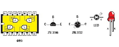
If you'd like the schematic diagram ("Figure 1") or component pinouts ("Figure 2") visualized, just let me know — I can create a clean diagram version for your blog.
Figure 2: Brochage du circuit intégré vu de dessus, des transistors vus de dessous et de la LED vue de face.Liste des composants
Ri 2,2M
R2 4,7 M trimmer
R3 2,2k
R4 10k
R5 2,2k
R6 100
R7 100
TRi.... PNP2N3906
TR2.... NPN 2N2222
ICi CD4093
DL1 ... LED haute luminosité
Si interrupteur
Montage proposé par Mr Virgil CASTELLI


