
If you've ever driven past road construction sites at night, you've likely seen the familiar sequence of flashing yellow lights that guide traffic. These aren’t just random blinks—they're carefully timed signals designed to catch attention and enhance safety. In this article, we’ll show you how to recreate that exact visual effect with an easy-to-build circuit using a NE555 timer and a CD4017 decade counter.
How It Works

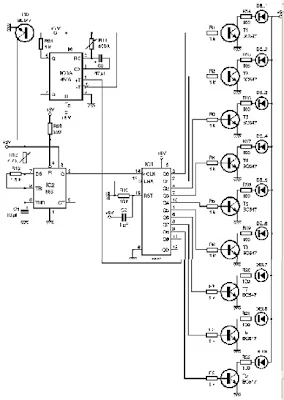
Once the CD4017 reaches its tenth output, it triggers a monostable 4538 IC, which briefly halts the timer circuit, simulating the pause seen in real road flash lights. After this pause, the cycle restarts from the beginning.
Key Components Used
-
IC1: NE555 Timer – generates the clock signal
-
IC2: CD4017 Decade Counter – controls LED sequencing
-
IC3: 4538 Monostable – creates a short pause after each full LED cycle
-
Transistors (BC547) – used to drive the LEDs
-
Yellow LEDs – simulate the real road beacons
-
Resistors & Capacitors – fine-tune flash speed and delay timing

Power Supply and Circuit Design
The circuit can be powered with a DC supply between +5V and +12V. It's designed with simplicity in mind, making it ideal for beginners and hobbyists alike. A PCB layout ensures a compact build, and standard DIP sockets are recommended for the ICs to avoid damage during soldering.
Adjustments:
-
R12 adjusts the speed of LED flashing (faster or slower).
-
R11 controls the duration of the pause after a complete sequence.
Practical Tips for Assembly
-
Use IC sockets for easy replacement and testing.
-
Ensure the first LED always starts the sequence using a simple power-on reset via R10/C2.
-
Don't forget the three jumpers (straps) on the PCB!
Component List (Quick Summary)
-
Resistors: From 1kΩ to 500kΩ (adjustable)
-
Capacitors: 1µF, 10µF, 47µF
-
LEDs: 9 yellow diodes
-
Transistors: 10 x BC547
-
ICs: NE555, CD4017, 4538
-
Power Supply: +5V to +12V DC
Why Build This?
Besides learning how ICs like the 555 timer and 4017 counter interact, this project gives a satisfying visual result that mimics a real-world application. It’s also a great conversation starter or showcase piece for anyone learning electronics.
Whether you're a student, educator, or hobbyist, this project is an excellent way to understand timing circuits, counters, and practical LED applications.


#ElectronicsProject #555Timer #CD4017 #LEDChaser #DIYFlasher #TrafficLightSim #ElectronicCircuits #TechDIY #MakerLife


