How to Read Resistor Color Codes: A Step-by-Step Guide
Resistors are important additives in digital circuits, limiting current flow and dividing voltages. To identify their values, manufacturers use a color-coding machine. Whether you are a beginner or an skilled hobbyist, knowledge those codes is critical.
1. The Basics of Resistor Color Coding
Resistors typically have 4 or 5 colored bands, each representing a specific value:
4-band resistors → Standard resistors (5% or 10% tolerance).
5-band resistors → Precision resistors (1% or 2% tolerance).
The first two (or three) bands indicate the significant digits, the next band is the multiplier, and the last band represents the tolerance.
2. Resistor Color Code Chart
Here’s a quick reference table:
| Color | Digit | Multiplier | Tolerance |
|---|---|---|---|
| Black | 0 | ×1 Ω | - |
| Brown | 1 | ×10 Ω | ±1% |
| Red | 2 | ×100 Ω | ±2% |
| Orange | 3 | ×1 kΩ | - |
| Yellow | 4 | ×10 kΩ | - |
| Green | 5 | ×100 kΩ | ±0.5% |
| Blue | 6 | ×1 MΩ | ±0.25% |
| Violet | 7 | ×10 MΩ | ±0.1% |
| Gray | 8 | ×100 MΩ | ±0.05% |
| White | 9 | - | - |
| Gold | - | ×0.1 Ω | ±5% |
| Silver | - | ×0.01 Ω | ±10% |
3. How to Read a 4-Band Resistor (Example)
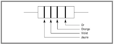
Take a resistor with Yellow, Violet, Orange, Gold bands:
Yellow (4) → First digit
Violet (7) → Second digit
Orange (×1 kΩ) → Multiplier
Gold (±5%) → Tolerance
Calculation: 47 × 1 kΩ = 47 kΩ (±5%)
4. How to Read a 5-Band Resistor (Example)
For a resistor with White, Orange, Brown, Black, Brown bands:
White (9) → First digit
Orange (3) → Second digit
Brown (1) → Third digit
Black (×1 Ω) → Multiplier
Brown (±1%) → Tolerance
Calculation: 931 × 1 Ω = 931 Ω (±1%)
5. Tips for Accurate Reading
Reading Direction: The tolerance band (gold/silver) is usually wider or spaced farther.
Use a Multimeter: For verification, measure resistance directly.
Practice: Test yourself with different resistors to improve accuracy.
Conclusion
Understanding resistor shade codes is essential for everyone operating with electronics. With this manual, you can optimistically become aware of resistor values and tolerances, ensuring correct circuit designs.
Figure 1.7 - Marking of a resistance at 1% or 2%. Each color corresponds to a number, as indicated in Table 1.3. It is necessary to pay attention to the reading direction: the last ring is a little separated from the others. Table 1.3 - Color coding for the marking of the resistors.Considérons un premier exemple (figure 1.8). Les deux premiers anneaux indiquent les chiffres significatifs de la valeur nominale de la résistance : jaune correspond à 4 et violet à 7. Le troisième anneau définit le multiplicateur : orange signifie × 1 kΩ. La résistance nominale est donc 47 kΩ. La précision est donnée par le quatrième anneau : or correspond à 5 %.
Figure 1.8 - Example of marking: resistance 47 kΩ, 5%. Let's take another example (Figure 1.9). It is a precision resistor since its marking has five bands. The first three indicate the significant digits of the nominal value: white, orange and brown, i.e. 931. The fourth band gives the multiplier: black means × 1 Ω. The nominal resistance is therefore 931 Ω. The tolerance is indicated by the last ring: brown for 1%.
Figure 1.9 - Example of marking: resistance 931 Ω, 1%.
#ResistorColorCode #ElectronicsGuide #OhmsLaw #DIYElectronics #ElectronicsBasics #ResistorBands


